Site-Directed Mutagenesis
Site-directed mutagenesis refers to any cloning technique where you introduce a specific, localized change into a DNA sequence. These changes may include:
- Substituting a base or codon
- Inserting or deleting a small sequence (typically <30 bp)
- Replacing a defined region
- Creating a variant library at a defined site
In all cases, you're targeting a specific location within a plasmid and rewriting a short region while leaving the rest unchanged.

Figure: Site-directed mutagenesis of the pTargetF plasmid to retarget the gRNA. The original cadA-targeting protospacer (orange) is replaced with a new cscR-targeting protospacer (pink), using a SpeI-flanked region upstream of the gRNA scaffold (green tracrRNA).
Overview of Mutagenesis Strategies
Most mutagenesis methods resemble the PCR-based cloning techniques you've already seen. The general pattern is:
- PCR the entire plasmid using primers that encode your intended mutations.
- Re-close the product using ligation or Gibson-like mechanisms.
- Transform and screen for correct clones.
Conceptually, it's like the limiting case of assembly: just one fragment, but edited.
1) EIPCR (Enzymatic Inverse PCR)
EIPCR is analogous to the NcoI/XhoI method you used in basic cloning, except it uses a single restriction site flanking the mutation site to reclose the plasmid.
This method is ideal when the mutation you want to introduce is close to a unique restriction site. You perform a full-vector PCR using primers that flank the site and introduce the desired edits. After PCR, you digest the product with the enzyme and ligate the linear fragment to restore circularity.
Example: Retargeting the protospacer in pTargetF
In the Basic Cloning tutorial, you cloned the Cas9 gene from Streptococcus pyogenes into an expression vector. Cas9 is the "scissors" protein that creates double-strand breaks at specific locations in DNA, but it requires a guide RNA (gRNA) to find its target. The gRNA consists of two parts: a customizable 20 bp protospacer sequence that matches the genomic target, and a constant scaffold that helps recruit Cas9. Together, the Cas9 protein and the gRNA form a complex that scans DNA, binds to sequences matching the protospacer, and cuts them if an adjacent "NGG" protospacer-adjacent motif (PAM) is present.
To design a new protospacer, you need to identify a 20 bp sequence in your target gene that is directly upstream of an NGG motif—the PAM site required by Cas9. In practice, you scan for "GG" on the 3′ end of the desired target, then take the 20 bp sequence immediately upstream. For example, if "GG" starts at position 101, the protospacer would be positions 80 to 99. You can think of this computationally as finding the index of "GG" and extracting the −21 to −1 substring. Any sequence that satisfies this rule can be targeted for cleavage by Cas9. To create a new gRNA, simply replace the 20 bp protospacer sequence in pTargetF and coexpress with Cas9.
The pTargetF plasmid expresses guide RNAs (gRNAs) for CRISPR/Cas9, combining a customizable 20 bp protospacer (which determines target specificity) with a constant scaffold region. To retarget Cas9 to a new genomic site, you simply replace the protospacer. Conveniently, pTargetF includes a SpeI site upstream of the protospacer, allowing efficient editing via EIPCR: PCR amplify the plasmid with primers encoding the new protospacer, digest with SpeI, and re-ligate to form the edited plasmid.
Primer Design and Strategy
The first step is to model your edited sequence. We want to replace the original cadA-targeting protospacer in pTargetF with a new protospacer targeting the cscR gene.
Below is a portion of the cscR sequence with all potential PAM sites (NGG) highlighted. Any 20 bp sequence immediately upstream of a GG can serve as a candidate protospacer. Specialized software tools can help you pick optimal guides based on efficiency and off-target predictions, and in many cases, validated guides are available in public databases.
Once you select your new protospacer, you replace the original cadA-targeting protospacer in pTargetF.
Below, we show the pTargetF sequence before and after the change. We also select forward and reverse anneal sequences flanking the site of modification.
Original (targeting cadA)
With cscR replaced
Now that we’ve modeled the edited region, we can design primers to build it. The forward primer includes everything from the SpeI site through the end of the forward annealing region. The reverse primer is the reverse complement of the sequence from the start of the reverse anneal to the end of the SpeI site. Add a 5′ tail of 5 arbitrary bases to both primers to improve enzyme activity and allow for efficient restriction digestion.
Forward Primer (ol_protoF)
        SpeI  Protospacer         Forward Anneal
5’-ccataACTAGTaacgcgtgaccgcgtattgcGTTTTAGAGCTAGAAATAGCAAG -3’

Reverse Primer (ol_protoR)
        SpeI  Reverse Anneal (rc)
5’-ctcagACTAGTattatacctaggactgagctag-3’
Finally, we can write up our construction file. As always, simulate your construction file to make sure it works before ordering oligos.
PCR       ol_protoF       ol_protoR       pTargetF      ipcr
Digest    ipcr                            SpeI          speDig
Ligate    speDig                                        pTarget-cscR
2) QuickChange Mutagenesis Using pET-INS
Example: C96S Mutation in Insulin
Cysteine 96 in human insulin helps form disulfide bonds critical for protein folding. Mutating this residue to serine (C96S) can stabilize recombinant insulin analogs by reducing misfolding or aggregation. In this example, we’ll use QuickChange mutagenesis to introduce the C96S mutation in the pET-INS plasmid.

Image adapted from Agilent Technologies.
Strategy
QuickChange uses two overlapping primers to introduce a mutation into a plasmid:
- The mutation sits in the middle of each primer.
- The flanking regions must perfectly match the template DNA.
- After high-fidelity PCR, the full plasmid is synthesized but with nicks.
- DpnI is used to digest the methylated parental (template) DNA.
- The nicked product is repaired inside E. coli after transformation.
Conceptually, this is like a Gibson assembly with one fragment, except ligation occurs in vivo.
Mutation Design
- Open
pET-INS.seqand locate amino acid 96 in the INS coding sequence. - Confirm it encodes Cysteine (TGC or TGT).
- Replace with a Serine codon, like AGC.
- Annotate the codon as
"C96S".
Primer Design
Choose ~20 bp of perfectly matched sequence flanking the mutation site for both directions. The mutation is centered in the oligos.
Oligos
Forward Primer (ol_C96S_F)
          [anneal]  [MUTATED CODON]  [anneal]
5’-gaagcgtggcattgtggaacaaAGTtgtaccagcatctgctccctc-3’

Reverse Primer (ol_C96S_R)
Reverse complement of forward primer
5’-gagggagcagatgctggtacaACTttgttccacaatgccacgcttc-3’
Final Notes
- Perform DpnI digestion after PCR to eliminate the template plasmid.
- No ligase is required — the cell repairs the nicks.
- Very fast and easy to perform
- Ideal for single codon changes, but less robust than EIPCR for large insertions.
3) Saturation Mutagenesis
When you began the wetlab portion of the pP6 experiment, you used Golden Gate-style site-directed mutagenesis not to create a single edited clone, but an entire library of variants. This approach is called saturation mutagenesis.
Instead of targeting one mutation, saturation mutagenesis introduces degenerate bases—for example, "N" represents a mix of all four nucleotides (A, T, C, G). There are other codes like:
"K"= G or T"S"= G or C"W"= A or T
These are called IUPAC degeneracy codes.
Designing these oligos follows the same workflow as any Golden Gate mutagenesis:
- Build a model of the final product with degenerate bases included.
- Define junctions and annealing regions.
- Simulate and confirm construct logic.
⚠️ However, a few special rules apply for degenerate libraries:
- Do not place degeneracy at the 3′ end of your oligos (the annealing region). This can prevent proper PCR priming.
- Avoid degeneracy at sticky ends. Keep the 4 bp sticky sequence constant, and also fix at least one adjacent base. Allowing diversity in this region can cause biased assembly.
- It's best to place degenerate bases a few nucleotides away from the junction to reduce any context-dependent ligation bias.
pP6 Promoter Library — Design Walkthrough
What this is: A promoter library built by iPCR/Golden Gate. We conserve the core promoter elements and randomize the surrounding bases to sample promoter strength and context.
Template: pJ12 (J23112 promoter → amilGFP). This vector already includes BseRI Golden Gate sites so the edited part can be mobilized later.
Design goals
- Conserve the –35, –10, and +1 elements.
- Randomize all bases between –35 to –10 and –10 to +1.
- Add 4 N’s on the left and right flanks of the promoter segment to increase diversity.
Step-by-step
You can download the pJ12 sequence here: pJ12.seq.
-
Open the template
• Start from pJ12, which carries the J23112 promoter.
• Change the –35 and –10 elements to their consensus sequences: TTGACA (–35) and TATAAT (–10).
• This ensures every variant in the library begins with promoter elements expected to be strong. -
Replace intra-promoter regions with N’s
• Randomize all bases between –35 to –10 and –10 to +1 by substituting with N characters of equal length.
• Change the 4 bp flanking both sides of the promoter segment to N. -
Choose the sticky end
• Pick a 4‑bp junction close to the randomized region, usually just to the left of it, leaving a base or two of separation.
• The sticky end should be in a conserved region so that all variants will produce the same overhang and close efficiently.
• For pP6, because we are introducing many changes, the assembly works better if the library is split in half. To do that, the junction is placed in the middle of the promoter.
• The –10 box (TATAAT) is conserved across all variants, so we chose the sticky end within that region for this case. -
Pick primer annealing regions (~20 bp)
• 5′ primer: just left of the randomized block.
• 3′ primer: just right of the randomized block.
• Follow design rules: balanced GC, avoid repeats, end in GC.
• Mark both annealing regions with a feature. -
Design the oligos
• From each annealing region, extend through to the sticky end.
• Forward oligo = sequence as-is.
• Reverse oligo = reverse complement of its region.
• Add required 5′ elements (tail, BsaI site, random base) as shown in the primer structure table below.
Primer structure (5′→3′) typically follows this pattern:
| Segment | Example | Purpose |
|---|---|---|
| 5′ tail | 5 bases | Padding to improve restriction enzyme efficiency |
| Restriction site | GGTCTC | Recognition site for BsaI |
| One base padding | 1 bp | Intentional extra base before the sticky; sets cut gap |
| Sticky end | 4 bp | Conserved overhang used for re‑closing |
| Buffer sequence | 1–2 bp | Fixed bases after the sticky end; prevents N’s from sitting directly next to the overhang |
| Randomized block | N… | Diversified bases between conserved elements |
| Anneal region | ~20 bp | Primer‑binding site (non‑randomized) |
- Write the construction file and simulate it to validate
PCR P6LibF2 P6LibR2 pJ12 P6
GoldenGate P6 BsaI gg
Transform gg Mach1 Carb 37 pP6
Video demo
Mutagenesis Quiz: Build a T204X EGFP Variant Library
In this quiz, you will design and simulate a saturation mutagenesis library at position 204 in EGFP. At this position, a threonine (ACC) has previously been shown—when mutated—to alter fluorescence properties. Here you’ll replace it with NNK to explore all possibilities.
Background
We're using pcDNA3-EGFP, a mammalian expression plasmid that produces Enhanced Green Fluorescent Protein (EGFP). This plasmid is commonly used for visualizing gene expression or localization in mammalian cells.
The plasmid contains:
- A CMV promoter for expression in mammalian cells.
- An Ampicillin resistance gene and ColE1 origin for propagation in E. coli.
- The EGFP gene, which encodes a protein that fluoresces green when expressed and excited with blue light.
In the lab, you'd build the plasmid in E. coli, purify plasmid DNA, and then transfect it into mammalian cells, where the protein is expressed and fluoresces.
Goal
In this quiz, you will design and simulate a site-saturation mutagenesis library at position T204 of EGFP. At this site the wild-type codon encodes threonine (ACC). By replacing it with an NNK codon you will create a library that samples all 20 amino acids (and one stop), enabling discovery of variants with altered fluorescence.
Tools
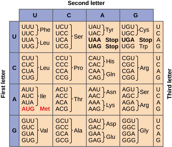
- 🧬 Genetic code table
- 📦 Benchling and ApE will translate sequences automatically — but you must start from the ATG of the ORF, not the start of the plasmid.
Task
-
Find the codon to modify
• Protein numbering starts at 1, so codon index = 3 × (position − 1).
• For T204: 3 × 203 = 609, so codon 204 spans bases 609–611 of the ORF.
• In EGFP, the threonine of interest is at codon 204 (bases 609–611), which is the ACC you should target.
• Confirm you have the correct codon by checking that it is ACC (threonine). -
Replace it with NNK
• Edit ACC (at codon 204, bases 609–611) → NNK. If your editor does not accept K, temporarily use NNN. -
Choose the 4‑bp sticky junction
• Pick 4 bp just to the left of the NNK (codon 204) site.
• Leave 1–2 fixed bases as a buffer between the junction and the NNK.
• Mark this 4‑bp feature. -
Choose annealing regions (~20 bp)
• On each side of the edited site (codon 204), select non‑randomized regions for primers.
• Follow standard rules (balanced GC, end with GC, avoid repeats).
• Mark both features. -
Design the oligos
• Forward oligo: [tail] + [BsaI site GGTCTC] + [one‑base padding] + [sticky end] + [buffer] + [NNK] + [anneal].
• Reverse oligo: reverse complement of its region with the same 5′ additions.
• Use the Golden Gate oligo pattern from the earlier tutorial as your guide. -
Correct NNN if used
• If you used NNN, change the last base to K to finalize NNK. -
Write the Construction File (CF) and simulate
Files
- You can find the plasmid here: Addgene #13031: pcDNA3-EGFP
- Click the "View all sequences" link on the Addgene plasmid page.
- Then click the GenBank download link.
- Open the downloaded
.gbkfile in ApE or Benchling to view the plasmid map and annotations. - A copy of the plasmid map is also available in the tutorial’s
assetsfolder as:addgene-plasmid-13031-sequence-305137.gbk.
⚠️ Important: The plasmid contains an internal BsaI site, which would interfere with assembly. To avoid this conflict, use BsmBI instead (recognition site: 5′–CGTCTC(N1/N5)–3′).